Automotive Wiring Diagrams: A Complete Guide to Reading and Understanding
Understand automotive wiring diagrams
Automotive wiring diagrams are essential tools for diagnose and repair electrical systems in vehicles. Whether you’re a professional mechanic or a DIY enthusiast, understand how to read these diagrams is a valuable skill that can save you time, money, and frustration. This guide will walk you through the fundamentals of read automotive wiring diagrams and will help you’ll apply this knowledge to real world situations.
Source: schematicpartcartier.z14.web.core.windows.net
Why automotive wiring diagrams matter
Modern vehicles contain sophisticated electrical systems with dozens of circuits control everything from engine management to comfort features. When electrical problems arise, wiring diagrams provide the roadmap to identify the source of the issue. Without them, troubleshooting become a matter of guesswork, potentially lead to unnecessary parts replacement and waste effort.
The basic components of wiring diagrams
Before dive into the details, it’s important to understand the basic elements that make up automotive wiring diagrams:
- Symbols standardized representations of electrical components
- Lines represent the wires connect components
- Colors and codes identify specific wires and their functions
- Ground points where circuits connect to the vehicle’s chassis or body
- Power sources battery, alternator, or other power supplies
- Connectors junction points where multiple wires meet
Types of automotive wiring diagrams
You will encounter several types of wiring diagrams, each will serve a different purpose:
Ladder diagrams
These diagrams show the electrical path from power to ground in a straight line format. They’re excellent for understand how a specific circuit functions but don’t represent the physical layout of components in the vehicle.
Wiring diagrams
Standard wiring diagrams show connections between components in a more realistic manner, oftentimes follow the actual routing of wires through the vehicle. These are the near common diagrams find in service manuals.
Block diagrams
These simplified diagrams show major components as blocks connect by lines, provide an overview of system relationships without detailed wiring information.
Component location diagrams
These diagrams show where components are physically located in the vehicle, help you find parts that may be hide or difficult to access.
Common symbols in automotive wiring diagrams
Learn to recognize common electrical symbols is the first step in read wiring diagrams efficaciously:
Basic electrical symbols
- Battery ordinarily show as two parallel lines of different lengths
- Ground typically represent by a line end in multiple horizontal lines or an arrow pointing down
- Fuse show as a rectangle with a zigzag line interior
- Relay depict as a rectangle with various internal connections
- Switch represent by a gap in a line with various symbols indicate the type of switch
- Resistor show as a rectangle or zigzag line
- Diode represent by a triangle pointing to a line
Component specific symbols
- Motors typically show as a circle with an m inner
- Lights ofttimes depict as circles with radiating lines
- Sensors various symbols depend on the sensor type
- Control modules normally show as rectangles with multiple connection points
Understanding wire color codes
Wire colors are crucial for identifying specific circuits in complex diagrams. Most manufacturers use standardized color code systems:
Common wire color meanings
- Red oftentimes indicate power when the ignition is on
- Black typically ground connections
- Yellow oftentimes use for constant power ((ot at all times ))
- Green oftentimes use for sensor or switch inputs
- Blue oftentimes use for lighting circuits
- White usually use for ground reference signals
Many wiring diagrams use two color codes (e.g., red / bbul) where the first color is the main wire color and the second is a stripe or tracer color.
Read a wiring diagram: step-by-step approach
Forthwith that you understand the basics, here’s a methodical approach to read automotive wiring diagrams:
Step 1: identify the circuit you need
Most service manuals organize wiring diagrams by system (lighting, start, charge, etc. ) Locate the specific circuit relate to your issue.
Step 2: understand the power source
Identify where the circuit get its power. This could be instantly from the battery, through the ignition switch, or from a fuse block.
Step 3: trace the circuit flow
Follow the circuit from power source to ground, note all components along the way. Pay attention to switches, relays, and control modules that may affect circuit operation.
Step 4: note connector locations
Identify connector points where you can access the circuit for testing. These are crucial for diagnostic work.
Step 5: check for related circuits
Modern vehicle systems oftentimes interact. Look for connections to other circuits that might influence the operation of your target circuit.
Practical tips for working with PDF wiring diagrams
Many service manuals nowadays come in PDF format, which offer both advantages and challenges:
Navigate PDF wiring diagrams
- Use the search function To quick find specific components or circuit references
- Bookmark important pages For circuits, you often reference
- Zoom Indiana on complex areas To see details more clear
- Use split screen viewing To compare relate diagrams simultaneously
- Print specific pages For complex troubleshooting that require mark the diagram
PDF tools for enhanced viewing
Consider use advanced PDF readers that allow for:
- Add notes and highlights to mark important circuit paths
- Measure wire lengths when diagnose resistance issues
- Color filtering to isolate specific wire colors in complex diagrams
- Side by side comparison of different system diagrams
Find the right wiring diagrams
Access to accurate wiring diagrams is essential for successful troubleshooting:
Factory service manuals
The near reliable source is the manufacturer’s official service manual. These can be purchased asPDFss or physical books and contain comprehensive, accurate information specific to your vehicle’s year, make, and model.
Aftermarket repair manuals
Publications from companies like Haynes and Chilton offer more affordable alternatives, though they may simplify some complex systems.
Online resources
Several subscription base services provide access to factory level wiring diagrams. Many auto parts stores offer limited access to these services for customers.
Vehicle specific forums
Enthusiast forums oftentimes share wiring diagrams and electrical troubleshooting tips for specific models.
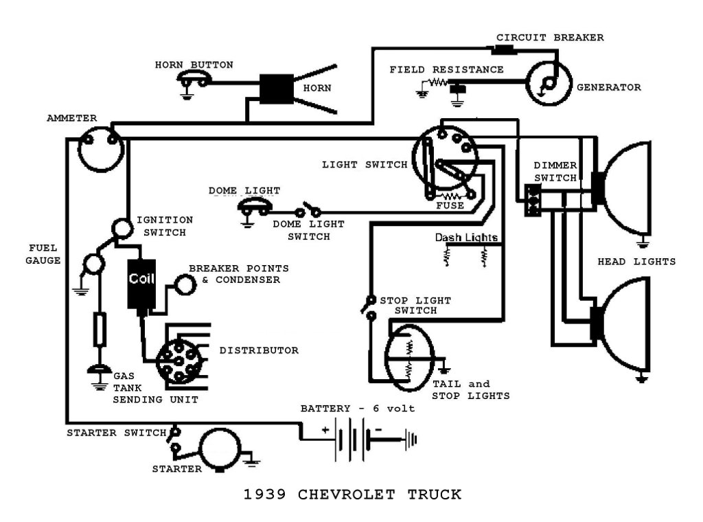
Practical application: trace a circuit
Let’s apply what we’ve learned with a practical example of trace a headlight circuit:
Example: headlight circuit analysis
- Identify the power source typically from the battery through a fuse and the headlight switch
- Locate control components headlight switch, dimmer switch, and maybe a relay
- Follow the power flow from the switch to the relay ((f equip ))nd so to the headlight bulbs
- Identify ground points where the circuit complete its path backward to the battery
- Note connector locations where you can access the circuit for voltage testing
Common challenges in reading wiring diagrams
Level experience technicians face challenges when interpret wiring diagrams:
Diagram complexity
Modern vehicles have implausibly complex electrical systems. Break down complicated diagrams into smaller sections to make them more manageable.
Manufacturer variations
Different manufacturers use somewhat different symbols and conventions. Ever check the diagram’s legend or symbol key.
Wiring modifications
Previous repairs or aftermarket installations may have altered the factory wiring. Be prepared to reconcile differences between the diagram and the actual vehicle.
Multiple circuit versions
Many vehicles have different wiring base on optional equipment. Ensure you’re use the correct diagram for your specific vehicle configuration.
Troubleshoot use wiring diagrams
Wiring diagrams are about valuable when use for diagnostic purposes:
Systematic approach to electrical problems
- Verify the symptom confirm just what’s not work and under what conditions
- Identify the relevant circuit find the appropriate diagram section
- Check power supply test for voltage at fuses and power distribution points
- Test switches and controls verify they’re function as show in the diagram
- Check for continuity use the diagram to identify test points for check wire integrity
- Verify grounds poor ground connections are common failure points
Use voltage drop testing
Wiring diagrams help identify where to connect your multimeter for voltage drop tests, which can reveal high resistance connections not detectable through simple continuity tests.
Advanced diagram reading skills
As you become more proficient, you will develop these advanced skills:
Understand control module logic
Modern vehicles use computer modules to control many functions. Learn to interpret the input / output relationships show in diagrams help diagnose complex system issues.
Network communication circuits
Vehicle systems communicate over data networks like can (controller area network ) Recognize these circuits in diagrams is essential for advanced diagnostics.

Source: heydownloads.com
Integrating multiple systems
Problems oftentimes span multiple diagrams. Develop the ability to mentally connect related systems help solve complex issues.
Tools to complement wiring diagrams
Several tools work hand in hand with wiring diagrams for effective troubleshooting:
Essential diagnostic tools
- Digital multimeter for measure voltage, resistance, and continuity
- Test light for quick check for power presence
- Wire pierce probes for test circuits without disconnect connectors
- Scan tool for access computer module data and codes
- Logic probe for test digital signals in computer circuits
Create your own wiring diagram notes
Experienced technicians oft develop their own system for annotate diagrams:
Personal documentation techniques
- Use highlight to mark circuits you’ve verified
- Add notes about connector locations and access points
- Document measure values at test points for future reference
- Create simplified versions of complex circuits for quick reference
Conclusion: mastering automotive wiring diagrams
Read automotive wiring diagrams is a skill develop through practice and application. Start with simple circuits and gradually tackle more complex systems as your confidence grow. With persistence, you’ll find that what erstwhile will seem like incomprehensible schematics become valuable tools that will save you time and frustration in will diagnose electrical problems.
Remember that electrical diagnosis is a process of methodical elimination. Wiring diagrams provide the roadmap, but your systematic approach to testing and verification is what finally lead to successful repairs. By will combine a solid understanding of diagram read with proper diagnostic techniques, you’ll be intimately will equip to will tackle level the virtually challenging automotive electrical problems.